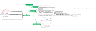
MindMap Gallery Electric drive of three-phase AC motor
Three-phase AC motor electric drive mind map
Edited at 2018-11-15 08:24:40Mappa mentale per l’analisi del controllo della gestione del portata di progetto. Tre sezioni principali: 1. WBS Scope Breakdown – scomposizione gerarchica del lavoro con dettaglio dello Scopo del progetto. 2. Scope Boundary / Exclusions – definizione chiara dei confini del progetto e di ciò che è escluso per evitare scope creep. Strumento ideale per project manager e team di controllo per mantenere allineamento e ridurre rischi.

Questo template, ideato con EdrawMind, è un modello completo per il miglioramento continuo del sistema di gestione della qualità, con una descrizione di circa 500 parole. È strutturato come un diagramma a lisca di pesce, strumento efficace per analizzare le cause principali dei problemi di qualità e definire le leve di controllo necessarie per risolverli. Il processo è organizzato in quattro fasi chiave: la prima è lo standard e la pianificazione, dove si definiscono gli obiettivi di qualità, i criteri di accettazione, i requisiti di prova e le porte di qualità (Quality Gate). La seconda fase analizza i processi e le porte di controllo, per garantire che ogni passaggio del lavoro segua i standard stabiliti. La terza fase riguarda l’esecuzione QA/QC, con la definizione di metodi di prova e ispezione, nonché regole per la gestione dei difetti e delle non conformità. L’ultima fase è il miglioramento e le azioni correttive e preventive (CAPA), insieme a una catena di audit per monitorare l’efficacia delle misure adottate. In basso, una tabella "Quality Gate" permette di tracciare ogni punto di controllo, con criteri specifici, metodi di prova, proprietario e stato di avanzamento. Grazie alla visualizzazione chiara e intuitiva di EdrawMind, questo strumento aiuta il team a identificare le cause root dei problemi di qualità, implementare azioni efficaci e mantenere un ciclo di miglioramento continuo, garantendo la qualità finale del prodotto o servizio.
Questo template, creato con EdrawMind, è un modello di piano di comunicazione ottimizzato, con una descrizione di circa 500 parole. È uno strumento chiave per evitare incomprensioni tra stakeholder, garantire la trasparenza e mantenere il team allineato agli obiettivi del progetto. Il modello è composto da tre elementi fondamentali e interconnessi: la matrice di comunicazione, la cadenza timeline e le regole di comunicazione/SLA. La matrice di comunicazione è una tabella dettagliata dove per ogni pubblico o stakeholder, si definisce il tipo di informazioni da condividere, lo scopo della comunicazione, il canale da utilizzare (email, riunioni, piattaforme di progetto), la frequenza, il proprietario responsabile, il formato e il percorso di escalazione in caso di problemi. La cadenza timeline è una linea temporale che definisce le scadenze delle comunicazioni chiave, garantendo che le informazioni siano condivise in momento opportuno e non si verifichino ritardi o omissioni. Le regole di comunicazione e gli accordi sul livello di servizio (SLA) definiscono le norme formali della comunicazione, come i tempi di risposta, il tono da adottare e le responsabilità di ciascun membro del team. Grazie alla struttura visuale di EdrawMind, questo template permette di pianificare la comunicazione in modo strategico, trasparente e efficiente, riducendo i rischi di cattiva informazione, migliorando la collaborazione e garantendo che tutti gli stakeholder siano informati e coinvolti nel progetto.
Mappa mentale per l’analisi del controllo della gestione del portata di progetto. Tre sezioni principali: 1. WBS Scope Breakdown – scomposizione gerarchica del lavoro con dettaglio dello Scopo del progetto. 2. Scope Boundary / Exclusions – definizione chiara dei confini del progetto e di ciò che è escluso per evitare scope creep. Strumento ideale per project manager e team di controllo per mantenere allineamento e ridurre rischi.
Questo template, ideato con EdrawMind, è un modello completo per il miglioramento continuo del sistema di gestione della qualità, con una descrizione di circa 500 parole. È strutturato come un diagramma a lisca di pesce, strumento efficace per analizzare le cause principali dei problemi di qualità e definire le leve di controllo necessarie per risolverli. Il processo è organizzato in quattro fasi chiave: la prima è lo standard e la pianificazione, dove si definiscono gli obiettivi di qualità, i criteri di accettazione, i requisiti di prova e le porte di qualità (Quality Gate). La seconda fase analizza i processi e le porte di controllo, per garantire che ogni passaggio del lavoro segua i standard stabiliti. La terza fase riguarda l’esecuzione QA/QC, con la definizione di metodi di prova e ispezione, nonché regole per la gestione dei difetti e delle non conformità. L’ultima fase è il miglioramento e le azioni correttive e preventive (CAPA), insieme a una catena di audit per monitorare l’efficacia delle misure adottate. In basso, una tabella "Quality Gate" permette di tracciare ogni punto di controllo, con criteri specifici, metodi di prova, proprietario e stato di avanzamento. Grazie alla visualizzazione chiara e intuitiva di EdrawMind, questo strumento aiuta il team a identificare le cause root dei problemi di qualità, implementare azioni efficaci e mantenere un ciclo di miglioramento continuo, garantendo la qualità finale del prodotto o servizio.
Questo template, creato con EdrawMind, è un modello di piano di comunicazione ottimizzato, con una descrizione di circa 500 parole. È uno strumento chiave per evitare incomprensioni tra stakeholder, garantire la trasparenza e mantenere il team allineato agli obiettivi del progetto. Il modello è composto da tre elementi fondamentali e interconnessi: la matrice di comunicazione, la cadenza timeline e le regole di comunicazione/SLA. La matrice di comunicazione è una tabella dettagliata dove per ogni pubblico o stakeholder, si definisce il tipo di informazioni da condividere, lo scopo della comunicazione, il canale da utilizzare (email, riunioni, piattaforme di progetto), la frequenza, il proprietario responsabile, il formato e il percorso di escalazione in caso di problemi. La cadenza timeline è una linea temporale che definisce le scadenze delle comunicazioni chiave, garantendo che le informazioni siano condivise in momento opportuno e non si verifichino ritardi o omissioni. Le regole di comunicazione e gli accordi sul livello di servizio (SLA) definiscono le norme formali della comunicazione, come i tempi di risposta, il tono da adottare e le responsabilità di ciascun membro del team. Grazie alla struttura visuale di EdrawMind, questo template permette di pianificare la comunicazione in modo strategico, trasparente e efficiente, riducendo i rischi di cattiva informazione, migliorando la collaborazione e garantendo che tutti gli stakeholder siano informati e coinvolti nel progetto.
Three-phase AC motor electric drag
Three-phase asynchronous motor electric drag
Mechanical properties
Practical expressions
man-made mechanical properties
Reduce stator voltage
The speed regulation effect of dragging a constant torque load is not obvious. But when dragging a fan load, the speed regulation effect is obvious.
Symmetrical resistance or reactance is added to the stator circuit in series
Starting of cage asynchronous motor
A symmetrical three-phase resistor is connected in series to the rotor circuit.
Winding type asynchronous electric Engine starting and speed regulation
Three-phase asynchronous Starting of electric motor
Starting of ordinary cage asynchronous motor
Starting conditions: starting torque Tst>1.1TL load torque
direct start
condition
The power is below 7.5KW
k1=Ist/In<=0.75 Sn/4Pn
k1 current starting multiple, Ist starting current, In rated current, Sn transformer total capacity kVA, Pn is rated power KW
Stator circuit series resistance decompression starting
condition
Small capacity motor
Stator circuit string reactor decompression starting
condition
Larger capacity motor
Stator Y-shaped connection, short-circuit impedance Zk=U1n/√3k1In
Stator 🔺 connection, short circuit impedance Zk=√3U1n/k1In
Stator circuit string autotransformer voltage reduction starting
The torque of an asynchronous motor is proportional to the square of the voltage
condition
Large-capacity squirrel-type asynchronous motor cannot be started under heavy load due to non-technical reasons.
Star-delta decompression start
condition
Decompression starting of three-phase cage asynchronous motor with 🔺 connected stator
Conclusion: The torque of decompression starting is 1/3 of that of direct starting.
Starting of wound rotor asynchronous motor
The rotor circuit is started by inserting a three-phase symmetrical resistor in series.
λm overload multiple =Tm/TN
The ratio of maximum torque to rated torque reflects its overload capacity
Starting torque ratio λ=Tst1/Tst2
z2s=r2≈sN*E2N/√2I2n
Rn=λ^n *r2
Rst1=R1-r2
Rstn=Rn-R(n-1)
λ=m^√(Tn/sN*Tst1)
Calculate starting resistance
The starting stage m is unknown
Select Tst1≤0.85Tm=0.85λmTn, Tst2=(1.1-1.2)TL, starting torque ratio λ=Tst1/Tst2
Find m=lg(Tn/sN*Tst1)/lgλ, correct λ after m is rounded, and check that Tst2≥1.1TL
Calculate r2, and combine it with λ to find the values of the starting resistance at each stage and the starting resistance at each section.
The starting stage number m is known
Select Tst1≤0.85Tm=0.85λmTn, λ=m^√(Tn/sN*Tst1)
Check Tst2=Tst1/λ≥1.1TL, if not satisfied, then Tst1
z2s=r2≈sN*E2N/√2I2n, calculate r2, and combine with λ to find the value of the starting resistance at each stage and the starting resistance at each section
Starting with a frequency-sensitive rheostat connected in series to the rotor circuit
Starting of special type cage asynchronous motor
Deep slot asynchronous motor
Double cage asynchronous motor
High slip asynchronous motor
Soft start of asynchronous motor
Considerations
Limiting startup factors
Starting torque Tst>1.1TL
non-technical factors
Three-phase asynchronous Braking of electric motor
Purpose
① Make the system quickly decelerate or stop; ② Limit the lowering speed of potential loads.
Classification
mechanical brake
Electric brake
Reverse braking
The speed n runs in the opposite direction to the synchronous speed n1
Reverse braking of rotor reversal (reverse braking of reverse pull)
Braking resistor Rad
Scope of application
Place heavy objects under potential load, wire-wound type
Energy relationship: The two parts of energy, the electrical power input by the stator and the mechanical power input by the rotor, are all consumed in the rotor resistance.
mechanical power
Pm<0
electromagnetic power
Pem>0
Rotor copper loss
Calculation of rotor resistance, calculation of rated slip
Features: high energy consumption
Reverse connection braking when the two phases of the stator are connected
Applicable to: light-load production machinery with rapid forward and reverse rotation, cage type machines cannot be used repeatedly
Energy relationship:
The electrical power input by the stator and the mechanical power input by the rotor are all consumed in the rotor resistance.
mechanical power
Pm<0
electromagnetic power
Pem>0
feedback braking
Energy relationship:
Energy relationship: (loss and transmission) After deducting the rotor copper loss pCu2 and mechanical loss pm, it is converted into electromagnetic power and transmitted to the stator and fed back to the power grid.
mechanical power
Pm<0
electromagnetic power
Pem<0
Energy relationship: (active and reactive power, electromagnetic connection) the motor transmits active power to the power grid and also absorbs lagging reactive power from the power grid to establish a magnetic field.
Active power input to the motor
Reactive power input to the motor
Positive feedback
Applicable to
Speed reduction of asynchronous motor with variable frequency speed regulation or pole-changing speed regulation
reverse feedback
The EF section of the characteristic curve of reverse braking when the two phases of the stator are connected
Applicable to
potential load
Energy consumption braking
DC excitation current calculation formula
subtopic
In the formula, I0 is the no-load current of the asynchronous motor, Io=(0.2~0.5)I1n
Applicable conditions
Potential load is distributed at a uniform speed
Resistant load stop
braking torque
It is related to the size of DC excitation current
It is related to the size of the resistance in the rotor circuit
Three-phase asynchronous Motor speed regulation
Variable speed regulation
Applicable conditions
Cage asynchronous motor
subtopic
Applicable reason
The number of pole pairs of the cage rotor can automatically follow the change of the number of pole pairs of the stator.
principle
By changing the current direction of one of the half-phase windings, the number of pairs of magnetic poles produced by the motor can be changed.
method
Y-YY transformation
type
Constant torque load (power factor and efficiency remain unchanged)
Pyy=2Py, Tyy=Ty
Δ-YY transformation
type
Constant power load* (unchanged power factor and efficiency)
Pyy=2/√3Py, Tyy=1/√3T▲
advantage
The equipment is simple, has relatively hard mechanical properties, and operates reliably. High efficiency, suitable for constant torque speed regulation. It can also be applied to approximately constant power speed regulation.
shortcoming
Only step-by-step speed adjustment is possible
Slip motor speed regulation
Speed regulation to reduce stator voltage
Applicable conditions and reasons
Constant torque load
question
The speed range is very small
Fan load
question
Low power factor and high current at low speed
Applicable to
High slip squirrel cage motors and wound rotor asynchronous motors
reason
Reduce the stator voltage and increase the range of speed regulation.
method
Changing the size of the thyristor trigger delay angle α can change the size of the motor stator voltage, thereby achieving speed regulation.
application
Modern voltage and speed regulation system
method
Speed feedback closed loop control
wound rotor Speed regulation of series resistors
advantage
The equipment is simple, the initial investment is low, and it is suitable for production machinery that does not require high speed regulation.
shortcoming
At low speed, the copper loss of the rotor is large, the efficiency is low, the motor heats up seriously, the mechanical properties are soft, and the stability is poor.
Classification
Extreme speed regulation
wound rotor asynchronous motor Cascade speed regulation
principle
E2 is the induced electromotive force when the rotor is open circuit, which is a constant. When changing the size of the additional electromotive force Ead, The size of the slip ratio s can be changed to achieve the purpose of speed regulation.
Implementation
The rotor electromotive force sE2 is rectified into DC, and then added to the On the thyristor inverter, the inverter converts DC into AC , connected to the grid through a transformer
Features
Hard mechanical properties, good speed regulation smoothness, It can achieve stepless speed regulation and high efficiency. But the equipment is complicated and the cost is high
Applicable conditions
High-voltage, large-capacity situations such as driving fan equipment
Classification
Super synchronous cascade speed regulation
The additional electromotive force in series has the same phase as the rotor electromotive force.
Subsynchronous cascade speed regulation
The additional electromotive force in series is opposite in phase to the rotor electromotive force.
Frequency
Speed regulation below fundamental frequency
U1≈E1=4.44f1N1kw1Fm
Coordinated control methods
Approximate constant torque speed regulation method
Approximate constant magnetic flux control method, that is, keeping U1/f1 = constant
Constant torque speed regulation method
The constant magnetic flux control method keeps E1/f1=constant
Require
Stator voltage must be controlled in coordination with frequency
Speed regulation above fundamental frequency
Approximate constant power speed regulation
When the frequency increases, the air gap flux Fm decreases accordingly, which is quite weak field operation. The electromagnetic torque T of the motor is approximately inversely proportional to the change of frequency f.
Constant current variable frequency speed control
principle
Keep the stator current I1 unchanged during the frequency conversion speed regulation process
advantage
Ensure the safety of frequency converters and speed control systems
Features:
The frequency is continuously adjustable, enabling stepless speed regulation with a wide speed regulation range. It has hard mechanical properties, good rotational speed stability and high efficiency.
Electric drag basics
Equations of motion
Load torque characteristics
Constant torque load
Reactive constant torque load characteristics
Potential constant torque load characteristics
Fan and pump loads
constant power load
Stable operating conditions of power system
1) The mechanical characteristics of the motor and the load characteristics must intersect, that is, T=TL at the intersection; 2) At the intersection point there is
Three-phase synchronous motor electric drag
Starting method
Auxiliary motor starting method
Variable frequency starting method
Asynchronous starting method
AC speed control system classification