MindMap Gallery OSI Seven-Layer Model Mind Map
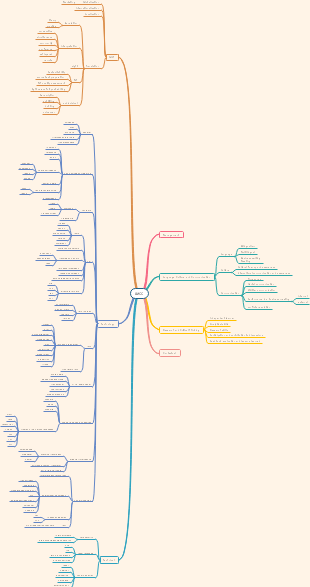
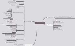
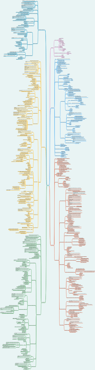
This is a mind map about ISO - OSI, Main content: layer 7 - APPLICATION, layer 6 - PRESENTATION, layer 5 - SESSIONS, layer 4 - TRANSPORT, layer 3 - NETWORK, layer 2 - DATALINK, layer 1- PHYSICAL LAYER.This OSI Seven-Layer Model Mind Map provides a comprehensive overview of the Open Systems Interconnection (OSI) Reference Model, one of the most fundamental concepts in computer networking. Designed for students, network engineers, IT professionals, cybersecurity practitioners, and certification candidates, this template organizes the complete OSI architecture into a clear visual framework, making it easier to understand network communication, protocol interactions, and layered network design. The mind map illustrates all seven layers of the OSI model, including the Physical Layer, Data Link Layer, Network Layer, Transport Layer, Session Layer, Presentation Layer, and Application Layer. Each layer is accompanied by its primary responsibilities, common protocols, data units, and networking technologies, enabling learners to build a complete understanding of how data travels across computer networks. The Application Layer introduces widely used protocols such as HTTP, HTTPS, CoAP, and HL7, demonstrating how applications communicate over networks. The Transport Layer focuses on TCP and UDP, explaining reliable and connectionless data transmission. The Network Layer covers IP, IPv4, IPv6, ICMP, routing algorithms, and packet forwarding mechanisms. The Data Link Layer explains Logical Link Control (LLC), Media Access Control (MAC), multiple access protocols, frame transmission, and error detection. The Physical Layer includes transmission media such as coaxial cables, twisted-pair cables, fiber optics, radio communication, microwave transmission, Wi-Fi, Bluetooth, modulation techniques, and physical layer protocols.
Edited at 2026-06-26 11:38:08ISO - OSI
1. layer 7 - APPLICATION
functions: provides interface for users 1. Mail services. 2. network virtul terminal 3. directory services 4. file transfer, access & management
HL7
https
coAP
2. layer 6 - PRESENTATION
3. layer 5 - SESSIONS
4. layer 4 - TRANSPORT
Transport Layer (Layer 4) is responsible for the end-to-end delivery of messages between hosts, ensuring data integrity and correct segmentation. Core Functions and Responsibilities 1. Segmentation and Reassembling: It divides large messages into smaller units (segments) for efficient handling by the network layer and reassembles them at the destination using sequence numbers. 2. Service Point (Port) Addressing: While the Network Layer gets packets to the correct computer, the Transport Layer ensures the message reaches the correct process (application) on that device using port numbers. 3. Connection Control: It can provide both connection-oriented (establishing a path first) and connectionless services. 4. End-to-End Flow and Error Control: It manages data flow to prevent overwhelming the receiver and performs error correction through retransmission to ensure the entire message arrives intact. Specialized Protocols for IoT and Health- two major protocols used in constrained environments (like medical sensors): 1. CoAP (Constrained Application Protocol): A RESTful protocol designed for small payloads over UDP. It uses a 4-byte header and supports four message types: Confirmable (needs ACK), Non-confirmable, Acknowledgement, and Reset. 2. MQTT (Message Queue Telemetry Transport): A publish/subscribe messaging protocol that is highly bandwidth-efficient. It offers three levels of Quality of Service (QoS): • QoS 0: Delivered at most once (no confirmation). • QoS 1: Delivered at least once (confirmation required). • QoS 2: Delivered exactly once.
TCP
Transmission Control Protocol (TCP) TCP is a complex, connection-oriented, and reliable protocol. Byte-Oriented: It treats data as a stream of bytes, numbering each one with a sequence number to ensure in-order delivery. Features: It provides full-duplex communication and implements flow, error, and congestion control. Key Header Flags: SYN/FIN: Used to initiate and terminate connections. ACK: Validates the acknowledgment field. URG: Indicates urgent data that should be processed immediately. RESET: Used to abort a connection if the receiver becomes confused.
UDP
User Datagram Protocol (UDP) is a "null" or "lightweight" protocol that provides an unreliable, connectionless service. Performance: It is faster than TCP because it lacks buffering and complex error-checking, making it ideal for real-time applications (like streaming) or simple request-response tasks. Capabilities: Unlike TCP, UDP supports multicasting and broadcasting. Applications: Commonly used for DNS, DHCP, and Network Time Protocol (NTP).

5. layer 3 - NETWORK
Network Layer (Layer 3) is the "controller" of the network, responsible for getting data from the source host to the destination host across multiple links or networks i.e ROUTING. 1. Core Role and Unit of Data Primary Function: It is responsible for routing signals through different channels from one device to another. Unit of Data: The data unit at this layer is called a Datagrams (packet). Scope: Unlike the DLL (node-to-node), the NL handles host-to-host delivery. 2. Key Responsibilities Routing: The most critical task is finding and maintaining a path from the source to the destination. Logical Addressing: It translates logical network addresses (like IP addresses) into physical addresses (MAC addresses). Switching: It is concerned with circuit, message, or packet switching to move data. Fragmentation: It breaks larger packets into smaller units if the next network cannot handle the original size. Congestion Control: It manages traffic to prevent "bottlenecks" when too many packets are present in the subnet simultaneously. 3. Hardware and Devices Routers and Gateways: These are the primary devices operating at the Network Layer to route packets to their final destination. 4. Design Issues and Challenges Routing Algorithms: Routes can be based on static tables (rarely changed) or can be highly dynamic (calculated for each packet based on current network load). Quality of Service (QoS): Issues such as delay, transmit time, and jitter are handled here. Internetworking: The layer must overcome differences between heterogeneous networks, such as different addressing schemes or maximum packet sizes. 5. NL provides services to Transport Layer: connection oriented & connectionless services to meet goals: – Service should be independent of router technology. – Transport layer should be shielded from number, type and topology of routers present. – Network address available at transport layer should use uniform numbering plan.
packets are called Datagrams & network is called Datagram Network
Main Functions
ROUTING is a core responsibility of the NL (Layer 3). Routing protocol is primarily concerned with finding and maintaining an efficient path for data to travel from a source to a destination. • Direct communication model: every sensor communicates directly (single-hop) with the sink device (base station) • Multi-hop communication model: sensors cooperate in propagating manner to send data towards the sink Key Responsibilities and Goals • Path Selection: The routing protocol must find and maintain the path from a sensor node to the "sink" (base station) • Energy Efficiency: transfer data with minimal power consumption to extend network lifetime • Fault Tolerance: Routing must adapt to hardware failures or environmental interference by re-routing packets through more stable or power-rich regions. Classification of Routing Protocols based on three main criteria: • Network Organization: - Flat: All nodes are treated as equals - Hierarchical: Nodes have different roles, such as cluster heads that manage transmissions for a group of member nodes - Location-based: Nodes rely on physical positioning information to route data • Route Discovery: - Proactive (Table-driven): Routes are established in advance before they are needed - Reactive (On-demand): A route is only found when a node actually has data to send • Protocol Operation: Includes methods like Negotiation-based (negotiating transfers first), Multi-path (using multiple routes simultaneously), and QoS-based (satisfying specific quality constraints)
ROUTING Algorithm
Routing Algorithms- is the specific software in the Network Layer that decides which output line a packet should use. If the network uses: 1. virtual circuit- decision of routing are made when circuit is being set up. 2. datagram- then routing decision is needed to be made for each arriving packet. Desirable properties include: • Correctness and Simplicity: Ensuring packets reach the right destination with low overhead. • Robustness and Stability: The ability to handle failures and topology changes without rebooting the whole network. • Fairness and Efficiency: Giving every node a chance to transmit while optimizing throughput and minimizing delay. Static vs. Dynamic Routing • Non-adaptive (Static): Routes are computed in advance and do not change based on current traffic or topology. • Adaptive (Dynamic): Routing decisions change in real-time to reflect the current state of the network. Specific Routing Techniques • Flooding: Every node broadcasts data to all neighbors. It is simple and reliable but highly inefficient due to "implosion" (duplicate messages) and "resource blindness" (ignoring energy levels) . • Distance Vector Routing: Each router maintains a table (vector) of the best-known distance to every other router and which link to use to get there. • Link State Routing: Routers discover neighbors, set cost metrics, and build a complete network map to compute the shortest paths . • Hierarchical Routing: Routers are divided into regions; a router knows everything about its own region but nothing about the internal structure of others, which saves table space. Routing Metrics To choose the "best" path, algorithms use various metrics: • Shortest Path: Minimum number of hops. • Energy Metrics: Minimum energy consumed per packet or maximizing the time until the network is partitioned. • Quality of Service (QoS): Considering latency (delay), throughput, and jitter. • Robustness: Assessing link quality and stability.
IP
• Internet Protocol is a NL protocol for logical addressing & routing of data packets between source & destination across interconnected networks. • its a connectionless protocol • It forms the core of TCP/IP suite & is used to move packets (datagrams) from one host to another, even across different physical networks. • works with Main Functions: 1. Logical addressing: assign a unique IP address to each device on the network and ensure correct identification of sender and receiver 2. Routing: determine the best path through the network to deliver packets 3. Fragmentation and reassembly: splits the large packets into smaller fragments to fit the network's maximum transmission unit (MTU) & Reassemble them at the destination. 4. Packet forwarding: Each router inspects the destination IP and forward packets to the next hop. 5. Error handling: IP itself does not guarantee error free delivery (unreliable, connectionless) uses ICMP for error detection. Reliability is handled by Upper layers. Structure of an IP packet 1. Header: contains control information such as source and destination addresses, version, TTL, checksum. 2. Payload (data): Actual data from the upper layer. Key Responsibilities of IP • Deliver packets from the source host to destination host. • Manage addressing fragmentation and routing • Handle time to Live to avoid endless looping. • Ensures inter network communication between different LANs/WANs IP address: is a 32-bit or a 128-bit logical number that uniquely identifies a device on a network. It is divided into network ID and host ID. Assigned manually (static) or automatically (DHCP).
IPv4
• IPv4, 4th revised version of IP, is a connectionless protocol used for packet-switched networks, such as Ethernet. • It operates on a best effort delivery model, in which neither delivery is guaranteed, nor proper sequencing or avoidance of duplicate delivery is assured. • It provides a logical connection between network devices by providing identification for each device. • IPv4 uses 32-bit (4 byte) addresses in five classes: A, B, C, D and E. Classes A, B and C have a different bit length for addressing the network host. Class D addresses are reserved for military purposes. Class E addresses are reserved for future use. • IPv4 addresses are written in the dot-decimal notation, which comprises of four octets of the address expressed individually in decimal and separated by dots (192.168.1.5.) Features: - 32 bit addressing - 4.3 billion addresses. - Supports fragmentation - Low Delay, High Throughput, Reliability (8 bits) - Simple and widely implemented - Uses address resolution protocol to map IP to Mac Limitations - Address exhaustion (not enough IPS for modern use) - No in build security - Manual configuration complexity - Poor support for mobility and QoS
IPv6
newer version of IP designed to replace IPv4, using 128-bit addressing to overcome IPv4's limitations.
Summary
 
6. layer 2 - DATALINK
Data Link Layer (DLL) is responsible for node-to-node (hop-to-hop) communication, transforming the raw transmission facility of the PL into a reliable link. Core Responsibilities and Design Issues The primary goal of the DLL is to provide a well-defined service interface to the Network Layer. Its specific duties include: - Framing: Organizing the bit stream from the PLr into manageable units called "frames" (packets or massages). FRAME contains frame header, a payload field for holding the packet, and a frame trailer). - Addressing: Adding physical addresses (MAC addresses) to the frame header to identify the sender and receiver. - Flow Control: Implementing mechanisms to prevent a fast transmitter from overwhelming a slow receiver. - Error Control: Detecting and correcting transmission errors to ensure data arrives in one piece. - Media Access Control: Determining which device has control over a shared link at any given time. Services Provided to the Network Layer The principal service is transferring data from the network layer on the source machine to the network layer on the destination machine. There are three common service types offered by the DLL: 1. Unacknowledged Connectionless Service: Independent frames are sent without acknowledgement. This is common in most LANs and for real-time traffic like voice. 2. Acknowledged Connectionless Service: No logical connection is made, but every frame is individually acknowledged. This is highly useful for unreliable channels like wireless systems. 3. Acknowledged Connection-Oriented Service: Machines establish a connection first. It guarantees that every frame is received exactly once and in the correct order. transfer is in 3 phases: estalishment of connection, actual transmission of frames, connection is released.
data is called Frame (packets/messages);
Main Functions
Sublayers
DLL Architecture (Sublayers) For many networks, particularly LANs, the DLL is split into two sublayers: 1. Logical Link Control (LLC): Provides an interface to the Layer 3 protocol and handles multiplexing/de-multiplexing and logical link services (connectionless or connection-oriented). 2. Medium Access Control (MAC): Manages access to broadcast media, frame formatting, and collision resolution.
Logic Link Control (LLC)
Medium Access Contro (MAC)
Medium Access Control (MAC) is a sublayer of the Data Link Layer. - The MAC sublayer sits between the Physical Layer and the Logical Link Control (LLC) sublayer of the Data Link Layer. - Its main responsibility is to regulate how a number of nodes access a shared (broadcast) medium. - Its goal is to determine "who gets to use the channel" when there is competition for it. Media Access Control (MAC) Sublayer Protocols When multiple nodes share a single channel (broadcast network), the MAC sublayer determines who transmits next. 1. Static Allocation: Methods like FDM (Frequency-Division Multiplexing) divide bandwidth into fixed portions. This can be wasteful if users are not constantly transmitting. 2. Dynamic Allocation: ALOHA: Users transmit whenever they have data; if a collision occurs, they wait a random time and retry. CSMA (Carrier Sense Multiple Access): Stations "listen" to the channel first. If it is busy, they wait; if idle, they transmit. CSMA/CD (Collision Detection): Stations abort transmission immediately if they detect a collision (used in Ethernet).
Protocols
Elementary Protocols: • An Unrestricted Simplex Protocol - we just send the data & dont care if it was received or lost • A Simplex Stop-and-Wait Protocol - we wait before sending to make sure there is an established connection & that our data will reach the destionation. • A Simplex Protocol for a Noisy Channel - to check for noise before sending the data 
Multiple Access protocols
Multiple Access Protocols - are the specific sets of rules or algorithms that live within the MAC sublayer to actually carry out the control. We can categorizes these protocols into several groups: 1. Random Access (Contention) Protocols: Users compete for the channel (e.g., ALOHA, CSMA, CSMA/CD). 2. Collision-Free (Controlled Access) Protocols: Users follow a strict order or schedule to avoid collisions (e.g., Bit-map protocol). 3. Limited-Contention Protocols: These combine the best parts of contention and collision-free methods, switching based on the network load. 4. Specialized Protocols: These include protocols designed specifically for Wireless LANs (to handle hidden/exposed station problems) or Wavelength Division.
Error
It is physically impossible for any transmission medium to be 100% perfect, as line noise (lightning, buildings, signal attenuation) is a constant factor. There are two main categories of errors: • Single-bit Error: Only one bit of a data unit is changed (e.g., from 1 to 0). • Burst Error: Two or more bits in a data unit are changed. The length of a burst error is measured from the first changed bit to the last. Error Detection vs. Error Correction Both detection and correction rely on redundancy, which means sending additional information along with the data. • Error Detection: Deciding whether the received data is correct without having a copy of the original message. • Error Correction: Detecting an error and then either requesting a retransmission or correcting it automatically. Error Detection Methods 1. Vertical Redundancy Check (VRC): Also known as a Parity Check. A single bit is appended to a data block to make the total number of 1s even (or odd). It can detect all odd-number errors. 2. Longitudinal Redundancy Check (LRC): Adds a Block Check Character (BCC) determined longitudinally through the message. It has a high success rate (98%) in detecting burst errors larger than 10 bits. 3. Cyclic Redundancy Check (CRC): A powerful technique based on polynomial arithmetic. It can detect all single and double-bit errors, any odd number of errors, and most burst errors. 4. Checksum: Used in IP, TCP, and UDP. Data is divided into segments and added using 1's complement arithmetic. If the result at the receiver is zero, the data is accepted. Error Correction Techniques: There are two main strategies for correcting data once an error is detected: 1. Backward Error Correction (Retransmission/ARQ): The sender resends the data. This is also known as Automatic Repeat Request (ARQ). Popular protocols include Stop-and-Wait ARQ, Go-Back-N ARQ, and Selective Repeat ARQ. 2. Forward Error Correction (FEC): The receiving device corrects the errors itself using redundant bits. This often involves: Hamming Distance: The number of bits that differ between two codewords. To correct d errors, a code must have a Hamming Distance of at least 2d + 1. Hamming Code: A scheme that can correct single-bit errors directly. Layer-Specific Error Control Error control occurs at multiple levels of the OSI model with different scopes: 1. Data Link Layer (Layer 2): Focuses on making data transfer error-free from one node to another (hop-to-hop). It uses trailers at the end of frames for this purpose. 2. Network Layer (Layer 3): Provides connection services that include network layer error control. 3. Transport Layer (Layer 4): Performs error control end-to-end to ensure the complete message arrives at the final destination without error. Retransmission is the primary method used here.
7. layer 1- PHYSICAL LAYER
Lowest layer of the OSI reference model. Responsible for sending bits from one device to another, but is not concerned with the meaning of the bits. Deals with 1. Setup of the actual physical connection of devices to the network 2. Transmission & reception of signals transmit raw bits (0s & 1s) 3. Base band and broadband transmissions Components: cables (Coaxial, Optical fibres, twisted pairs), connectors, hubs, repeaters, Network interface cards, Physical Topologies, (bus, mesh, ring star, tree) Key Functions to Remember - Bit Representation: Data in this layer consists of stream of bits. Bits must be encoded into signals for transmission. It defines a type of encoding (how 0s & 1s are encoded into electrical or optical signals). - Data Rate: The speed of transmission (bits per second- bps) - Synchronization: Ensures the sender & receiver are synchronized at the bit level. - Interface: Defines the Transmission Interface between devices and transmission medium. Features: - Line configuration: This layer connects devices with the medium in 1. point-to-point configuration and 2. multi point configuration - Topologies: devices must be connected in bus, star, ring, mesh, tree topology. - Transmission Modes: PL defines the direction of transmission between two devices. Simplex: One direction only. Half Duplex: Both directions, but only one at a time. Full Duplex: Both directions simultaneously. Design Issues - Mechanical & Electrical specifications - Data rate & transmission of raw bits over the communication channels - Synchronisation between transmitter and receiver; that is when one side sends 1 bit it is received as 1 bit by the other side and not as a 0 bit. Example: Ethernet physical standard, USB, Bluetooth, Wi-Fi. Importance: Foundation of all the higher layers- Ensures signals are transmitted properly through the medium.
data is called Bit
Network topologies
Schematic description of a network arrangement, connecting various nodes(sender and receiver) through lines of connection. Phases of deployment: Pre-deployment and deployment phase – Sensor nodes can be either thrown in mass or placed one by one in the sensor field Post-deployment phase – Sensor network topologies are prone to frequent changes after deployment Re-deployment of additional nodes phase – Addition of new nodes poses a need to re-organize the network TYPES Bus: All devices connect to a single cable. Transmits data only in one direction. (linear bus topology -has exactly two end-points). It is cost-effective but if the main cable fails, the whole network goes down. Star: All devices connect to a central hub(central node). Hub acts as a repeater. If the hub fails, the network fails; however, a single cable failure only affects one node. Fast performance, easy to troubleshoot. Ring: Forms a ring. Each device has exactly two neighbors. Uses repeaters to prevent data loss over long distances. Transmission is unidirectional but can be made bidirectional- Dual Ring topology: 2 connections between each Network Node. Two ring networks are formed, and data flow is in opposite direction in them. Not affected by high traffic but troubleshooting is difficult. Mesh: Point-to-point connection. Every device is connected to every other device (Full Mesh). It is highly robust and provides security & privacy, each connection carries its own data load. Installation & configuration is difficult & cabling is very expensive (n(n-1)/2 channels for n devices). Types: partial mesh & full mesh. Uses 2 techniques for data transmission: Routing - nodes have a routing logic, as per the network requirements, like routing logic to direct the data to reach the destination using the shortest distance. routing logic which has information about the broken links, and it avoids those node routing logic to re-configure the failed nodes. Flooding - the same data is transmitted to all the network nodes. The network is robust, and the its very unlikely to lose the data. But it leads to unwanted load over the network. Tree: has a root node, and all other nodes are connected to it forming a hierarchy (aka hirarchial topology). Has atleast 3 levels. Ideal if workstations are located in groups. Used in Wide Area Network (WAN). Easy to manage & maintain, expand nodes, detect errors. Costly, heavily cabled & network fails if the central hub (root node) fails. Hybrid: Combination of two or more types of topologies. Inherits the advantages and disadvantages of the topologies included. Reliable as troubleshooting & error detection is easy. Effective, flexible & scalable. But design gets complex & costly.
Bus
Star
Ring
Mesh
data transfer techniques
Routing
Flooding
Tree
Hybrid
Transmission medium
Transmission medium is the means through which we send our data from one device to another. Cables: are the medium through which information usually moves from one network device to another. The type of cable chosen for a network is related to the network's topology, protocol, and size. Transmission Media (Cables) types: Twisted Pair (UTP/STP): Most common. Uses RJ-45 connectors. Coaxial Cable: Single copper conductor with a metal shield to block interference. Uses BNC connectors. Fiber Optic: Transmits light through glass fibers. Single Mode: Long distance, higher cost. Multimode: Larger diameter, high bandwidth over shorter distances.
modes
bounded medium
Coaxial
 TYPES • Thinnet: Thin coaxial cable. 10Base2: thin coaxial cable carrying Ethernet signals. The 2 refers to the maximum segment length being 200 meters (185meters). Used in linear bus networks. • Thicknet: Thick coaxial cable. 10Base5: thick coaxial cable carrying Ethernet signals. The 5 refers to the maximum segment length being 500 meters. They have an extra protective plastic cover that helps keep moisture away from the center conductor. This makes thick coaxial cables a great choice when running longer lengths in a linear bus network. D/A: does not bend easily and is difficult to install. Connectors used: Bayone-Neill-Concelman (BNC) connector. Different types of adapters are available for BNC connectors, including a T-connector, barrel connector, & terminator. Connectors on the cable are the weakest points in any network. To help avoid problems with network we can use the BNC connectors that crimp, rather screw, onto the cable.
baseband
broadband
Fibre optics
• Consists of a central glass core surrounded by several layers of protective materials. It transmits light rather than electronic signals, thus eliminating the problem of electrical interference. • Ideal for environments that have large amount of electrical interference & connecting networks between buildings, due to its immunity to the effects of moisture and lighting. • Has the ability to transmit signals over much longer distances & higher speed compared to coaxial and twisted pair making communication possibilities to include services such as video conferencing and interactive services. • Cost is comparable to copper cabling; however, it is more difficult to install and modify. • 10BaseF refers to the specifications for fiber optic cable carrying Ethernet signals. 
Twisted pairs
Twisted pair cabling comes in two varieties: Shielded and Unshielded. - Unshielded twisted pair (UTP) is the most popular and is generally the best option for school and simple networks. Quality may vary from telephone-grade to extremely high-speed cables. The cable has four pairs of wires inside the jacket. Each pair is twisted with a different number of twists per inch to help eliminate interference from adjacent pairs and other electrical devices. The tighter the twisting, the higher the supported transmission rate and the greater the cost per meter. Categories: 1-8 (5e & 6a). Uses RJ-45 connector (registered jack). Maybe susceptible to radio and electrical frequency interference - Sheilded twisted pair (STP) used were cables are needed to be placed in sensitive environments with lots of potential interference or susceptible to electrical currents. they help extend maximum distance of the cables. STP are available in three different configurations: – Each pair of wires is individually shielded with foil. – There is a foil or braid shield inside the jacket covering all wires (as a group). – There is a shield around each individual pair, as well as around the entire group of wires (referred to as double shield twisted pair). Sheilding types: using aluminum strips, or foil and tinned copper braid, covering the twisted pair; for higher categories that work at high frequencies also with foils that cover the individual pairs, so as to improve both the overall shield and the NEXT values (i.e. to reduce interference between one pair and the other).
Unshielded
Sheilded
1. Cat 5e (U/S): freq upto 100Mhz. used for Fast Ethernet & Gigabit Ethernet. 2. Cat 6 & 6e(U/S): freq upto 250 MHz & 500 Mhz, resp. Used for network protocols such as Fast Ethernet, Gigabit Ethernet, & 10 Gigabit Ethernet. 3. Cat 7(S): freq upto 600 MHz. Used for transmission of network 10 Gigabit Ethernet protocols over 100m of copper cables. 4. Cat 7A(S): freq upto 1000 MHz & even higher (1200 - 1500 MHz). used for transmission on 10 Gigabit Ethernet over 100m. 5. Cat 8 (S): freq upto 2000 MHz. Fast Ethernet, Gigabit Ethernet, & 10 Gigabit Ethernet.
unbounded meium
Radio
Microwave
Wireless
ISM Bands: "Industrial, Scientific, Medical" bands are unlicensed frequencies. They are used for short-range & low power wireless communications systems like cordless phones, WiFi, Bluetooth, NFC, RFID, wireless dones, mics, baby monitors & alarm systems.
Modulation
 Modulation: the process of encoding information from a message source in a suitable way for transmission over the channel & is achieved by altering the characteristics of a wave. Data transmission can be done by superimposing a message on to a high frequency signal known as a carrier wave (or sinusoidal signal). The modulation process involve two waves: – The Modulating Signal (baseband signal) and the Carrier Signal (sinusoid signal). – The output of the modulation process is called as the Modulated Signal Analog Modulation: AM, FM,PM Digital Modulation Types: done for a better quality & efficient communication. Advantages over analog: bandwidth, high noise immunity, & permissble power. ASK (Amplitude Shift Keying): Varies amplitude; very susceptible to noise. FSK (Frequency Shift Keying): Uses two different frequencies for 0 and 1; more robus than ASK. PSK (Phase Shift Keying): Shifts the phase of the wave; more efficient for high data rates. QAM: A combination of ASK and PSK used in modern high-speed WiFi.
PL Protocols
WiFi
Wireless Fidelity (trademark) used to ensure compatibility between equipment from different manufacturers. - IEEE 802.11 is the technical standard that defines the protocols for wireless local area networks (WLANs). - operates across the 2 bottom layers of the OSI model using a "Multiple Over the Air PHY" architecture with "one common MAC". 1. Physical Layer (L1) – Frequencies and Modulation • WiFi utilizes unlicensed Industrial, Scientific, and Medical (ISM) bands, primarily at 2.4 GHz and 5 GHz. Newer versions also use 6 GHz and 60 GHz. • It uses various digital modulation techniques to send data: • Basic: BPSK, QPSK, 16-QAM, and 64-QAM. • Advanced: Modern WiFi uses OFDM (Orthogonal Frequency-Division Multiplexing) for multi-carrier modulation and OFDMA (for WiFi 6) to allow multiple users to share a single channel. • High Density: WiFi 6 utilizes 1024-QAM for maximum data throughput. 2. Data Link Layer (L2) – Medium Access Control (MAC) • Unlike Ethernet's collision detection (CSMA/CD), WiFi uses Carrier Sense Multiple Access with Collision Avoidance (CSMA/CA). • Because wireless channels are inherently unreliable, WiFi uses an Acknowledged Connectionless service where individual frames are acknowledged and retransmitted if lost. • To solve wireless-specific problems like the Hidden Station Problem (where two stations can't hear each other but both can hear the access point), it can use the MACA protocol involving Request-to-Send (RTS) and Clear-to-Send (CTS) frames. Major WiFi Generations: Wifi 4, Wifi 5, Wifi 6. Special Versions & Specialized Uses - 802.11s (Mesh): Creates wireless distribution systems with automatic topology learning and dynamic path configuration. - 802.11ah (HaLow): Operates at 900 MHz for long-range (up to 1 km) and low power consumption. - 802.11ad/ay: Operates at 60 GHz for extremely high-speed, short-range data (up to 20 Gbps).
Bluetooth
Major Types: Classic vs. BLE They are 2 incompatible types of bluetooth that often co-exist on a single "dual-mode" device like a smartphone: Bluetooth Classic (BR/EDR): Used for streaming high-bandwidth data like audio in headsets and car systems. It operates over 79 RF channels. Bluetooth Low Energy (BLE): Introduced in version 4.0, it is designed for low-power, battery-operated IoT sensors that transfer small amounts of data infrequently. It operates over 40 RF channels. Operates in both Physical Layer (PHY) and Data Link Layer (DLL) - Bluetooth operates in the freq of 2.4 GHz ISM band (2.400 - 2.4835 GHz). - The spectrum is divided into 40 channels that are 2 MHz wide. This includes 3 fixed Advertising Channels (for discovery) and 37 Data Channels (for connected communication). - It uses Frequency Hopping Spread Spectrum (FHSS), allowing devices to switch frequencies to avoid interference and congestion, hence making it highly reliable. - The primary modulation used is (Gaussian Frequency Shift Keying) GFSK. - All packets contain a Preamble (1 byte), Access Address (4 bytes), Payload (2-39 bytes), and a 24-bit CRC for error detection. Stack Architecture (BLE)- The BLE stack is split into two independent parts, often connected via a standardized Host Controller Interface (HCI): - Controller: Handles the "hard" real-time physical layer packets and timing. It includes the Physical Layer and the Link Layer . - Host: Runs the higher-level logic and is more relaxed in its timing. It includes: L2CAP: Manages fragmentation and recombination of large packets . Security Manager (SM): Responsible for device pairing and key distribution. Generic Access Profile (GAP): Defines device roles (Broadcaster, Observer, Central, Peripheral) and manages connection establishment . Generic Attribute Profile (GATT): Defines the hierarchical structure of data using Services (groups of attributes) and Characteristics (specific data values). Evolution: Bluetooth 4.2 vs. Bluetooth 5.0 - Speed: Supports a new 2 Mbps mode, twice as fast as the 1 Mbps limit of 4.2. - Range: Offers 4x the range (up to 200m outdoor) through "Coded PHY". - Advertising Capacity: Provides 8x the capacity (255 bytes vs. 31 bytes), which has made Bluetooth Beacons much more popular for shopping malls and parking. - Power: Bluetooth 5.0 is noted as having even lower power requirements and better battery life.
error message

ICMP